
Waste to Energy
Sicomo
The Sicomo CHP plant which is located about an hour’s drive from Beirut across Mount Lebanon in the Bekaa Valley. It supplies process steam and electricity to the adjoining recycling paper mill. The mill processes waste paper to produce compressed carboard for packaging. Residues from the recycling process are used to fuel the CHP plant along with other locally supplied waste streams. Plant Operations commenced 2014 Thermal only. CHP operations commended September 2016. Combustion is with a step grate close coupled gasification furnace with extended secondary chamber coupled to a linear waste heat type water tube boiler arrangement with integrated cassette type super heater supplying steam to a multistage extraction and condensing steam turbine rated to 3.1 MW.

Running is continuous with shut downs once a month for 2-3 days depending on needs, mostly cleaning of boilers, checking grate lamellas and superheater tubes. Current testing of a pulse air/ultrasonic cleaning system is yielding positive results and when installed in all boiler sections will reduce downtime for cleaning.

Running is continuous with shut downs once a month for 2-3 days depending on needs, mostly cleaning of boilers, checking grate lamellas and superheater tubes. Current testing of a pulse air/ultrasonic cleaning system is yielding positive results and when installed in all boiler sections will reduce downtime for cleaning. The plant burns between 5.5 to 6.5 tonnes per hour of waste and produces up to 18,000 kg of steam at 40 barg 375 deg C steam for process and power generation. Process steam is extracted from the turbine at 7 barg. Power output from the Triveni steam turbine varies between 1 and 3 mWh depending on steam demand from the paper mill. There is no electricity tariff available, so the CHP plant is run to match the mill demand only. Ash from the process is non-hazardous and flue stack emissions which are continuously and independently monitored are below European requirements, with notably low SOx and NOx levels.

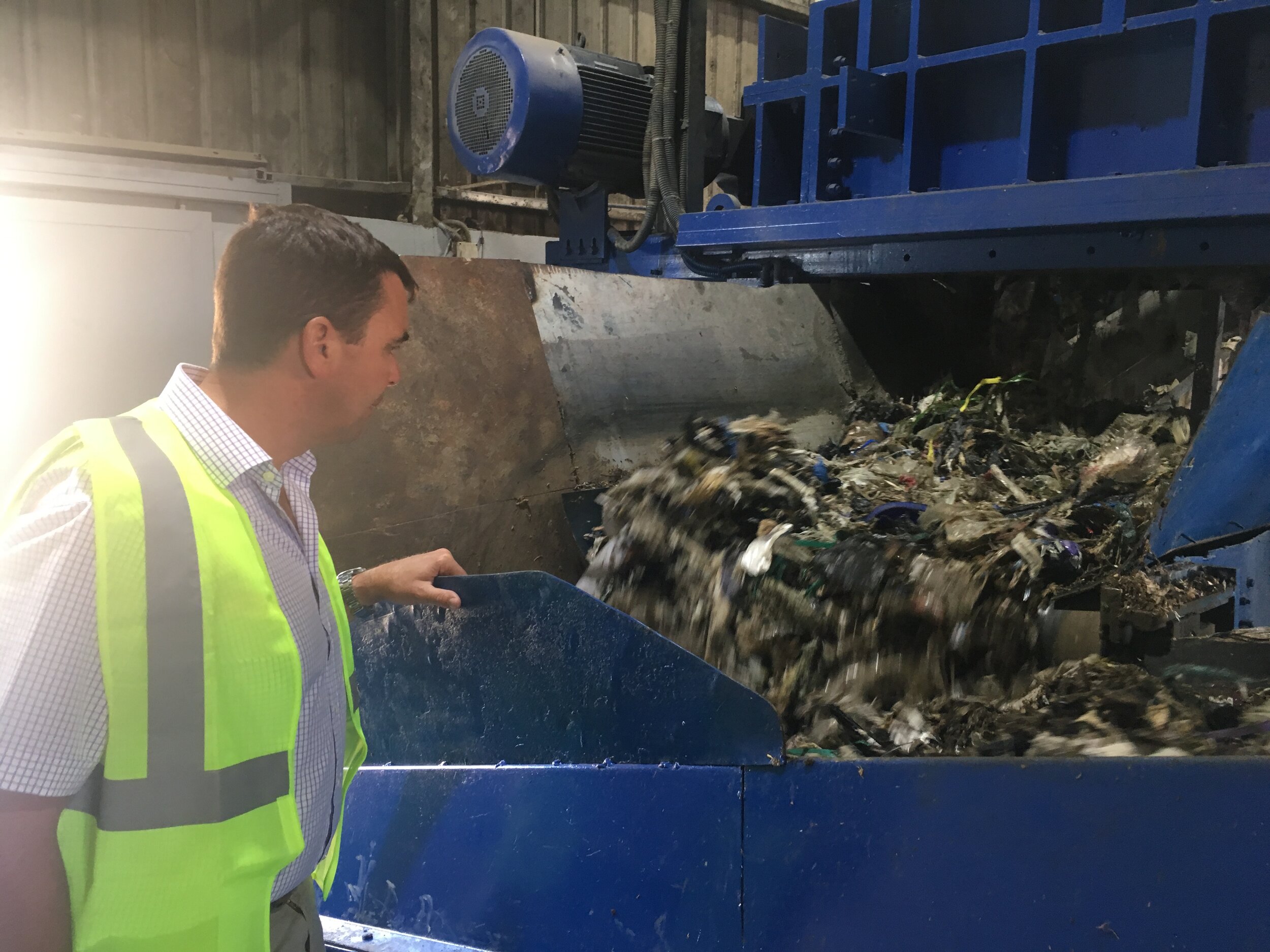
Fuel: combination, industrial/building waste paper, packaging and plastics and unsorted household domestic waste. On the day of the site visit non-sorted, non-shredded domestic waste was being loaded directly into the fuel feed system. The industrial/building waste was shredded in a slow speed shredder before combing with the domestic waste. Both streams were combing on the furnace infeed conveyor belt. Management said they are beginning to segregate and mix waste streams to ensure a more consistent calorific value as the domestic waste has a high food content with moisture contents ranging from 30% to 50% in winter.
Fuel Feed & Handling, Industrial waste is feed directly to a slow speed shredder, a magnetic separator is over the belt feeding a rotating screen. On the day of the site visit the screen was bypassed, it is only used in winter to remove fines to help reduce overall moisture content.
The domestic waste was discharged directly from the refuse trucks into the covered fuel store. The fuel store is a covered building measuring approximately 30 X 40m with an operator controlled overhead gantry grab crane feeding duty standby conveyors going to the furnace.
Furnace Infeed; The fuel is dropped through an inverted hopper into the feed chamber of the furnace, the side of the feed chamber is opened at high level to enable an operator to rake the fuel material level. (Note this setup differs from the Irish Furnace which has an upper chamber where the fuel is distributed by means of a hydraulic pusher before being discharged on demand in to the fuel feed chamber. This function is automated requiring no operator intervention. It also means the fuel infeed is sealed preventing tramp air entering ensuring better combustion control.) Primary Combustion; Underneath the fuel a stoker ram ejects the fuel material onto a step grate. The step grate works on a continuous basis moving the fuel forward and down as is burns. Ash falling between the grate is captured by a chain conveyor in a water bath underneath unburned material and remaining ash falls from the last grate section into the water bath chain conveyor. The ash is discharged to an ash house via a chain conveyor to the side of the furnace. There was a small percentage of combustible material in the ash. The ash is screened removing combustible material back to the fuel store and metals for recycling by others. The attached reports give details of the ash chemical content. Laboratory tests (attached) on concrete made using both bottom ash and fly ash demonstrate that there is no leaching from the concrete. Plans are at an advanced stage to incorporate the ash into concrete for building purposes.
==

Combustion and heat recovery; Gases from combustion enter an extended combustion zone via a restricted opening created by a separation wall between the step grate chamber (primary) and the secondary chamber. Secondary air is added at this point increasing the combustion temperature to greater than 850 deg C. On the day of the visit the temperature range across this chamber was from 950 deg C to 1229 deg C. To comply with EU WID the residence time in the secondary combustion chamber is 2 seconds at 850 deg C minimum. From the secondary chamber the combustion gasses enter the heat recovery section first the water tube screen boiler then super heater section on to the evaporators and economizers. Each boiler section has a water membrane wall. The boilers were manufactured in India and delivered to site in shipping containers. Steam from the evaporator section is gathered in a steam drum located on top and is then fed to the superheater below. A boiler water spray attemperator is used to control the super heater temperature before the steam enters the Triveni Steam Turbine. The steam that is not extracted from the turbine for process is condensed in a shell and tube condenser underneath. Cooling water for the condenser is supplied from an Mesan evaporative cooler located in the building

Flue Gas Treatment; Flue gasses exiting the boiler are dosed with sodium bicarbonate to react with the Chlorine gasses producing NaCl (& H2O) thereby eliminating the formation of Hydrochloric Acid and its corrosive effects either in the flue gas path or at the emission point. (Note the attached emission test results are without sodium bicarbonate dosing hence the elevated levels of HCL. After dosing the flue gas is filtered in the bag filter enclosure and on to the flue stack via the duty-standby induced draft fans. The flue stack emissions are continuously monitored using SICK (German) continuous dust monitoring sensors (scattered light measurement principle) and by the self-calibrating Evea (French) Multi-gas analyser for flue gas analysis.

Manning. Max staff per shift seven. The CHP plant has three operators per shift, one based in the control room and one on the floor to sampling and testing boiler water, feed water, coolers and chemical levels and equipment function checks. The third is based at the furnace fuel hopper manually levelling the fuel as it enters the furnace. The reception, processing and storage area has four operators, reducing to one at night the duties are loader operators, grab crane operation and general yard duties. Note the level of automation in the Sicomo plant is significantly less than the Irish plant where the plant ran for prolonged periods without anyone present on site. However, with a fuel as inconsistent as the waste handled by the Sicomo Plant some level of manning will be required to monitor the plant the fuel feed. Building. The building is steel portal frame measuring 30 meters wide by 90 meters and 12 meters at the eaves. it encloses all parts of the CHP plant including the cooling tower. The fuel store is approximately 30 X 40 meters. The fuel processing is 20 X 10 meters.
